FX40 with monitor

电化学显微镜 (EC-AFM)

带有电化学表征的表面高分辨率成像

In EC-AFM, STM the nanoscale structures of electrochemical reactions on the electrode surface can be observed. Users typically perform voltammetry and corrosion experiments using an electrochemistry cell and a choice of potentiostat/galvanostat depending on the electrochemical application of interest.

Electrochemical atomic force microscopy (EC-AFM) combines high-resolution imaging of surfaces with electrochemical characterization. EC-AFM is operated in a liquid environment containing electrochemical reactive species. A set of electrodes allows applying a bias to the sample where electrochemical reactions can occur depending on the magnitude and direction of that bias while an AFM setup measures the surface morphology and subsequent changes to it.

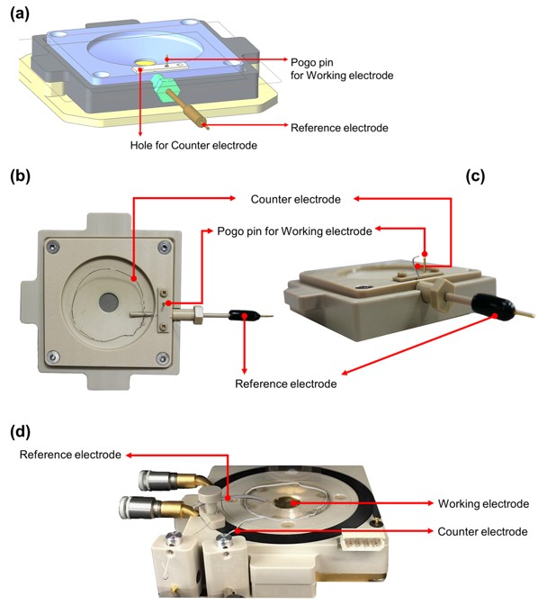
Such measurements are realized with the EC cell that is designed to simultaneously perform EC reaction while providing a suitable medium to image the topography of the sample surface. This cell is similar to the setup used for standard measurements in liquid environments with the main difference that the EC cell is also equipped with three electrodes: the working, counter, and reference electrode (Figure 1). The working electrode applies the bias to the (semi-) conductive sample surface, where the reaction of interest occurs in the EC measurement system. The counter electrode is needed to close the electric circuit. Its main function is to enable a flow of current, e.g. to dispose or receive electrons from the electrolyte. An inert material like Pt wire is typically used for the counter electrode to avoid unwanted side reactions at its surface. The reference electrode operates as a feedback sensor to maintain a constant potential applied to the working electrode and the counter electrode. This reference electrode needs a well-known and stable electrode potential, that is commonly achieved by buffered or concentrated redox systems like Ag/AgCl or H/H+. These three electrodes are connected to a potentiostat to either apply a defined bias while monitoring the current flow or a constant current while monitoring the bias to perform typical electrochemical experiments like cyclic voltammetry (CV) measurements to study electrochemical reactions. In addition, it is possible to select a certain bias to enforce a specific oxidation or reduction reaction at the sample surface. A high ohmic connection between the working electrode and the reference electrode ensures, that any measurable current mainly flows between the working electrode and the counter electrode and thus can be attributed to specific electrochemical reactions.

ModeNote ec afm fig1

Figure 1. EC-Cell (a) schematic drawing, (b) top view, (c) side view of EC-Cell, (d) Universal liquid cell with EC toolkit.

These electrochemical reactions can be studied both via the CV measurements as well as through AFM measurements that visualize any changes to the sample topography. It is recommended that the cantilever is made from an inert material to avoid any side reactions or changes to the tip geometry. Moreover, the cantilever needs to be electrically insulated to avoid unwanted stray currents.

An example of EC-AFM measurement is the deposition and dissolution of Cu nanoparticles on the Au surface while sweeping the bias in CuSO4 /H2SO4 solution. Cu ions are reduced at the Au surface to form elemental Cu when a negative bias is applied via the working electrode, providing an excess of electrons (Eq. 1). Accordingly, elemental Cu oxidizes upon applying a positive bias to the Au surface, removing electrons via the working electrode (Eq. 2).

Cu2+ + 2e- → Cu0…… Eq. 1. Reduction reaction, Cu deposition
Cu0 → Cu2+ - e-…… Eq. 2. Oxidation reaction, Cu dissolution

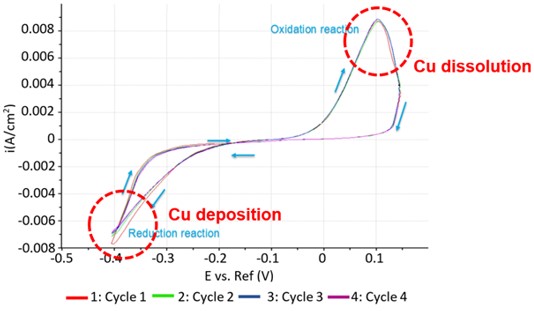
Such reduction/oxidation reactions were conducted and monitored by measuring the CV curve, while the deposition/dissolution of Cu particles on the Au substrate was confirmed with AFM. Figure 2 shows four CV curves taken with the working electrode in a solution containing 0.1 mM CuSO4 in 50 ml of 0.01 mM H2SO4. Cu nanoparticles started to form on the Au surface at an applied bias of -0.2 V with the highest reduction current flowing at -0.4 V. These Cu particles started to oxidize and dissolved upon reversing the bias as indicated by a current flow starting at 0 V and peaking at ~0.1 V. The absence of current flow at an applied bias of -0.1 V indicates an equilibrium state wherein no chemical reaction occurs. Moreover, the overlap of four consecutive scans indicated complete reversible redox reactions.

ModeNote ec afm fig2

Figure 2. CV curves of reversible Cu deposition on Au surface.

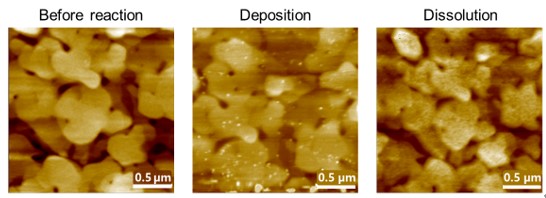
The Cu nanoparticle formation and dissolution were conformed via AFM images in Figure 3 showing the Au surface ‘Before reaction’, after ‘Cu deposition’, and after ‘Cu dissolution’. All images were obtained in the Non-contact mode of AFM in liquid condition using a soft cantilever (PPP-CONTSCR with spring constant of 0.2 N/m and resonance frequency of 25 kHz). Figure 3 ‘Before reaction’ AFM image shows a pristine Au surface without any particles. After the deposition of Cu occurred, the Au surface exhibited Cu particles as depicted in Figure. 3 ‘deposition’. These Cu particles were fully reoxidized after being subjected to a positive bias.

ModeNote ec afm fig3

Figure 3. Cu nanoparticle deposition on Au surface. AFM images of pristine Au surface ‘Before reaction’,
after reduction at -0.4 V ‘Cu deposition’, and after oxidation at 0.1 V ‘Cu dissolution’.

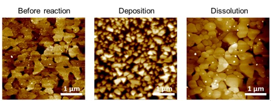
The nature of the occurring redox reactions as well as the change of surface morphology can be influenced by choice of parameters. In a subsequent set of experiments, -0.6 V was applied to the Au surface submerged in Cu2+ solution to deposit larger Cu clusters (Figure. 4). This Cu cluster formation was fully reversible as indicated by a completely exposed Au surface after applying 3 V for 5 min.

ModeNote ec afm fig4

Figure.4. Cu layer deposition on an Au surface. AFM images of Au surface ‘Before reaction’, after reduction at -0.6 V ‘Cu deposition’,
and after oxidation at 3 V ‘Cu dissolution’. All images were recorded in the same area.

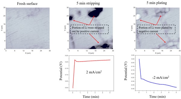
Another example of EC-AFM measurement is presented in the following paragraph. In this study, the EC reaction of an electrolyte containing Li ions with Li metal was investigated when applying a constant current density of ±2 mA/cm2 while monitoring the required bias. Changes in the Li metal surface were measured by AFM before and after a positive and negative bias was applied. The working, counter, and reference electrodes were all Li metal whereas the electrolyte was 1 M lithium bis (trifluoromethanesulfonyl) imide (LiTFSI) in tetraethylene glycol dimethyl ether (TEGDME). To prevent oxidation of Li metal at ambient conditions, all measurements were conducted in an argon-filled glovebox. Before applying the bias, the pristine Li metal surface was imaged showing a smooth surface. After applying a bias of approximately 0.2 V, the Li surface was etched as parts of the metal surface were stripped over a period of 5 min (Figure. 5). Subsequently, Li-ions were deposited in the same area while applying a negative bias (Figure 5). The potentiostat enabled tracking of the gradual increase in positive or bias to maintain a current density of ±2 mA/cm2, confirming the stripping and plating reactions.

ModeNote ec afm fig5

Figure 5. Li electro-stripping/plating measurements

EC-AFM measurement can be applied to various research and industrial fields owning to its ability to observe surface morphology change during EC reaction. The utility of EC-AFM is especially useful in battery research or metal corrosion and corrosion protection study where EC and surface properties are key factors.